Domite Welding Guide
- Ensure that the Domite® backing plate and mating metal surface is clean and flat.
- Welding Rod selection;
- Low hydrogen weld rods or gas covered cored wire is recommended.
- Gas shielded solid MIG wire – Ø 1.2mm max
- Flux cored wire – Ø 1.6mm max to ASTM/AWS A5.18 classification ER705-6
- Low hydrogen electrode – Ø 3.25mm max t ASTM/AWS A5.1 classification. E7016-1H8 or E7018-1H4
- Do not pre-heat Domite®.
- Clamp and tack weld Domite® into position.
- Stitch weld, laying 50mm maximum length on each run, alternating ends or sides to minimize heat input.
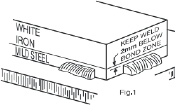
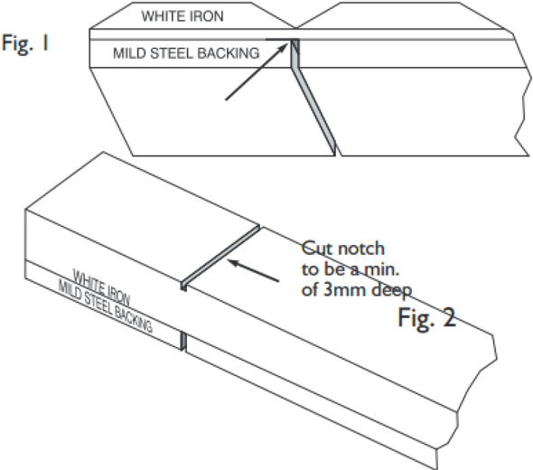
- Do not deposit weld within 2mm from joint line between Domite® and steel backing plate, as shown in Figure 1.
CAUTION. Temperature must not exceed 200°C. Excessive heat input may cause cracking and delamination. Use thermal crayons to monitor temperature. Do not weld continuously – Continuous weld may cause warping, delamination, and cracking. If a complete peripheral weld is required, use stitch weld procedure as per step 5.
Contact us for more welding guidelines, specifically related to joints and Bucket Armour components.
Domite Cutting Guide
High pressure abrasive water jet cutting is the preferred cutting method. Thermal cutting using an oxyacetylene torch, arc-air or plasma is NOT recommended due to high localized heat input and high risk of cracking and delamination.
For Domite® no greater than 25mm section thickness, cutting by abrasive disc is an accepted practice.
CAUTION. Extreme care must be taken when cutting to minimise local pre-heating or cracks and delamination may occur.
Cutting Procedure < 25mm Section Thickness
- Secure the Domite® piece to be cut in a vice or clamp.
- Notch the backing plate as shown in Figure 1.
- Notch the White Iron a minimum of 3mm deep opposite the
notch in the backing plate, as per Figure 2. - Wrap the Domite® with a rag and carefully hit using a soft faced
hammer. The piece should break cleanly at the notch.
Note: The deeper the notch in the White Iron, the cleaner the break.
Domite Forming Guideline
This practice is suitable for Chocky bars.
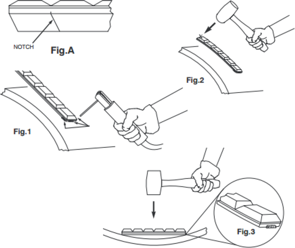
NOTE: For severe curves with a radius of less than 305mm, or inside curves, it is advisable to notch the mild steel backing plate opposite the ‘V’ to assist forming (Figure A). The Chocky Bar may crack during bending. This is normal.
- Clean the surface to which chocky bar will be welded.
- Tack weld one end of the chocky bar (as per the welding procedure) in at least 3 places by 15mm minimum length per weld (Figure 1)
- Outside Curves: Hammer down unwelded end of bar with a soft face hammer to bend bar to match mating radius. (Figure 2)
- Inside curves: Starting in the center strike bar with a soft face hammer to bend bar to match mating radius. (Figure 3)
- Stitch weld as per the weld procedure.
Product Safety
Any fitting or fabrication work should be carried out in accordance with applicable site safety standards, ensuring use of approved hard hats, eye protection, steel-toed shoes and protective gloves. Always use a soft faced hammer when performing the work as described in these instructions.